Radiologia Brasileira - Publicação Científica Oficial do Colégio Brasileiro de Radiologia
AMB - Associação Médica Brasileira CNA - Comissão Nacional de Acreditação
 Vol. 45 nº 2 - Mar. / Apr. of 2012
|
ORIGINAL ARTICLE
|
|
Computational toolkit for evaluating air kerma with the purpose of radiation protection of hospital inpatients: proposal of a simple experimental evaluation method |
|
|
Autho(rs): Gabriela Hoff1; José Rodrigo Mendes Andrade2; Andréia Caroline Fischer da Silveira Fischer3; Alexandre Bacelar4 |
|
|
Keywords: Radiology; Radiological protection; Software toolkit. |
|
|
Abstract: INTRODUCTION
Software tools such as CalDose(1), Mirdose(2), Olinda/EXM(2), Echo® DoseResponse Software(3) and Rad Pro Calculators( 4) have been utilized to support radiological protection in medical practices involving the use of ionizing radiations. Generally, such tools are aimed at generating useful dosimetry data of patients who are being exposed to ionizing radiation. The current dose assessment models for diagnosis applications define that biological effects may be directly related to increased risk for developing adverse effects such as cancer(5,6), among others. However, when one works with scattered radiation, the models' complexity increase for low doses and low dose rates(7,8). Currently, a consensus is still to be reached on a method to calculate or estimate the additional risk posed by scattered radiation to professionals and patients who are close to diagnostic X-ray sources. Thus, the principle to be observed is minimizing radiation exposure while maximizing the benefits to the patient. Additional exposure caused to inpatients by scattered radiation originated from procedures for other patients do not bring any direct or indirect benefits and should be avoided or minimized. In seeking to protect individuals, one utilizes dosimetric quantities to assess the amount of radiation exposure that such individuals may be exposed to. In the present study, kerma and ambient dose equivalent were selected as dosimetric quantities for both data input and output. Radiation exposure is the dosimetric quantity which measures the amount of ionization produced by X-radiation or &947; in the air. It can be directly quantified by means of the response from ionization chambers. Air kerma was selected as data input for the worksheets for being an easily measurable quantity by means of the usually available measurement devices found in Brazilian hospitals and clinics. Air kerma is defined as the initial kinetic energy of all charged particles released by non charged ionizing particles in a defined air mass. It can be calculated through exposure and is related to patient dosimetry. The kerma measurement/determination may be utilized as a form of assessing risk to individuals, as the higher the kerma, the greater is the dose to the individual. Such a relationship can be defined by means of factors of kerma conversion into effective dose, computationally calculated or determined on anthropomorphic phantoms. The ambient dose equivalent (at a point in a radiation field) is equivalent to the dose that would be produced by an aligned and expanded field in a spherical ICRU phantom at a determined depth, in the radius opposite to the direction of the incident radiation beam. This is a dosimetric quantity which is directly related to the application of radiologic protection and can be utilized to evaluate whether the area may be considered as radiation free, according to the Portaria 453/98(9). This is an information of great importance in the field of radiologic protection, with radiation free areas being those where the levels of ambient dose equivalent is lower than 0.5 mSv/year(9). Such areas, by definition, are exempted from specific radiological protection controls or utilization of dosimeters( 9). The main objective of the present study is to generate a computational toolkit, since now named toolkit, and method to measure dosimetric quantities which will be useful for protection of inpatients in environments where mobile radiation emitting apparatuses are utilized, thus raising new questions on the application of radiological protection, and seeking also to protect those patients who are not being directly exposed to ionizing radiation, but might be receiving radiation doses on account of the hospital environment where they stay. The present study presents the initial assessments and mappings for this type of investigation. Generally, there is not a direct dose limitation, but only a recommendation of reference levels for patients who are being submitted to clinical procedures. However, in the case of inpatients, it is possible that other forms of irradiation are present, particularly the exposure to secondary radiation produced by mobile X-ray generating apparatuses. Those patients may receive increased dose equivalent because of such unintentional "additional exposure" caused by scattered radiation originated from procedures performed in "neighboring" patients. The assessment of such additional dose is relevant to guarantee patients' safety and the lower unintended exposure to ionizing radiation as possible during inpatients stay, considering that such kind of exposure does not bring any direct benefit to the patient. The non-observance of this radiological protection principle leads to inappropriate application of the ALARA (As Low As Reasonable Achievable) principle, which establishes that the radiation dose should be as low as possible to produce the desired diagnostic data. The direct application of the ALARA principle can be undertaken by means of the assessment of ambient dose equivalent maps (generated by the toolkit presented in this study) and the pursuit of the positioning of beds and stretchers in safe areas (classified as radiation free areas according to Brazilian standards). For such a purpose, it is necessary to know the mapping of the ambient dose equivalent mapping or air kerma so that radiological protection measures can be put into practice. The Brazilian Regulations(911) define the dose threshold for occupationally exposed individuals (20 mSv/year), but the patients constitute a special class of individuals to whom the ALARA principle as well as cost-risk-benefit considerations(12) are more noticeably applied. Generally, professionals working in areas where mobile emitting apparatuses are utilized are not classified as occupationally exposed individuals. The present study applies both to patients and non-occupationally exposed individuals who stay in areas where mobile X-radiation emitting apparatuses are utilized. In the field of radiological protection, it is of utmost relevance to assure maximum benefit and minimum risk during medical exposure to ionizing radiation. Thus, the considerations in the present study cover not only the exposure originated from radiologic procedures performed on the patient, but also possible additional doses originating from radiologic procedures performed in other inpatients in a same hospital environment in cases where routine examinations are performed by means of mobile apparatuses. Such considerations also address the safety of non-occupationally exposed individuals who must remain in the areas where the mobile apparatuses are utilized, by assuring that they position themselves in the so called radiation free areas. Thus, the present study conceives a methodological proposal which is easily applicable and a toolkit for data management for calculating or mapping air kerma and ambient equivalent dose in hospital bed areas. The toolkit has been validated and, in addition to exposure/mAs data collected for mobile apparatuses hereinafter denominated shape factor, it allows the customization of input data with the purpose of calculating the above mentioned dosimetric quantities. MATERIALS AND METHODS A toolkit was created in order to manage experimental data originated from exposure measurements and generate an air kerma map (related, in this case, by a factor of 1 with the ambient dose equivalent) for scattered radiation around the hospital bed during a radiologic procedure performed with a mobile apparatus. The authors did not utilize a programming language, but rather the generation of active Excel® worksheets with the utilization of plain resources (without the need for activating external macros). The Materials and Methods chapter will be presented by means of two different sub-chapters: the determination of the method utilized for generating the shape factors for the assessment of ambient dose equivalent and air kerma, and the presentation of the toolkit with the options for data input and output. Exposure data collection For the creation of the ambient dose equivalent assessment model for different X-ray generating apparatuses, three apparatuses were selected, as follow: a MUX 10 model Shimadzu and two Polymobil 10 Siemens. Such apparatuses were initially evaluated with respect to their accuracy and repeatability of the air kerma rate and acceleration/ tension; accuracy and linearity of exposure time; collimation and alignment of the central radiation beam; as well as testing for and were also investigated for leakage radiation in the tube housing assembly. All the assessed apparatuses presented good utilization conditions, and were in compliance with the minimum Brazilian standards. The exception was one of the Siemens apparatuses (serial number 1809990X055I), which presented issues both in alignment and collimation of the radiation beam. The testing results were forwarded to the institution management, and repairs were duly performed before the data collection. The data collection strategy was defined in such way to utilize resources that are commonly available in hospitals. The only data collection information that can be added in the generation of shape factors for the study of scattered radiation is the integral (or total) exposure collected in mAs at positions of interest on the mesh-grid. A mobile X-ray emitting apparatus, a secondary radiation measuring device, a scattering object and a support in order to attach the ionization chamber at the same height are required to perform the measurements. In order to make the method accessible, the selected scattering object was a non-anthropomorphic acrylic phantom measuring (30.0 × 30.0 × 20.0) cm3, which may be utilized to simulate the chest or the abdomen (depending upon the added acrylic thickness), containing an aluminum rod measuring (2.0 × 1.5 × 30.0) cm3 to simulate the spine. Such a phantom has been utilized for repeatability testing in X-ray generating devices and comparative equipment evaluation, following the recommendations for non-anthropomorphic phantoms( 1315). Early in the present study, data were collected from three apparatuses utilized in two hospitals in the city of Porto Alegre, RS, Brazil, in the usual operating conditions in such institutions (93 kVp and 100 kVp). In case one wishes to utilize data considering different peak voltages, all that is necessary is to follow the method described in the next paragraphs and utilize the data personalization mode of the developed tool. In the development of the proposed method a data collection area of 4.2 m × 4.2 m was considered, with the central reference point in the two-dimensional Cartesian coordinates system corresponding to the central beam entry point on the primary radiation field. The non-anthropomorphic phantom was placed on a support (a stainless steel table) and positioned in an empty examination room, allowing the exposure measurements on the defined mesh-grid and the mapping of the area of interest. One should highlight that the phantom support could be made from other materials. The authors have opted for a stainless steel table as it was easily available in the data collection environments and presented appropriate dimensions for data collection in the phantom's surrounding areas. Certainly, such a support increased the amount of scattered radiation, an acceptable fact for conservative studies approaching dosimetry and radiological protection. From the central reference point, measurements of the integral exposure were performed at 0.3 m increments, forming up a grid in a plane at the medial level of the phantom. Seven measurements were performed in each direction of the area of interest, so as to reach a distance of 2.1 m to each side of the plane, as shown on Figure 1. The data collection points were marked on the room floor with adhesive tape. 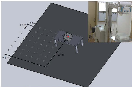 Figure 1. Illustration of the data collection geometry showing the utilized material and the measurement mesh-grid (only one of the four measurement quadrants is highlighted), with the measurements being performed at the level of the phantom center. The red marked zone refers to the center of the collection, and the remaining zones refer to the other collection points. The exposure measurements data collected on the mesh-grid do not take into consideration the contribution of caused by the patient, who receives the additional dose, i.e., it is a free-in-air measurement. In the present study, the radiation exposure was measured by means of a duly calibrated specific ionization chambers for secondary radiation beams. Radcal (model 1800CC) ionization chambers and electrometers were utilized for measurements with the Shimadzu equipment, while with the Siemens apparatuses, Victoreen (model 660-5) devices were utilized. The characteristics of the selected radiographic techniques were dependent upon the limitations of each apparatus, with the 96 kVp and 40 mAs technique being utilized for the Siemens apparatuses and the 100 kVp and 63 mAs technique being utilized for the Shimadzu equipment. The differences in such techniques result from limitations of each apparatus and technique utilized in the participating hospitals. In order to minimize the variations caused by mAs differences in the collection, the data were normalized for exposure/ mAs. Such normalized measurements on the mesh-grid points were named shape factor (SF), as they serve as basis for determining the intensity of the dosimetric quantities calculated by the toolkit. The calculation model proposed in the developed toolkit considers the above described data collection geometry. Once the SFs are determined, they can be utilized to estimate the air kerma and the ambient dose equivalent for the different workloads in the service and months of inpatients stay. The toolkit allows the users to enter customized SF data. Thus, users can collect the measurements on the exposure/mAs meshgrid according to the above described method for different tube voltages, entering such data as the "My shape factor (SF)" option is selected in the "Select shape factor (SF)" item available on the worksheet. The tool Among the available possibilities of implementation, the authors have opted for the ActiveData worksheets. The ActiveData is a user-friendly resource, providing results soon after the data input. The developed worksheet can be utilized with different softwares, with such possibility being verified with Excel®, BrOffice and Gnumeric. The proposed structure of the developed toolkit is quite simple, as it comprises two worksheets as follows: Data_base (Base_ de_dados) (which is occult for security purposes) and Calculation_worksheet (Planilha_de_cálculo). The Data_base (Base_de_dados) worksheet contains the proposed "database" with the SFs (mR/mAs) for the collected data grids and the mobile apparatuses. The data included in such worksheet were collected from previous studies(16,17). The worksheet which is available (visible) to the user is the Calculation_worksheet (Planilha_de_cálculo). This is the actual user interface worksheet, which requests the user to enter the following data: mean tube current transported by examination (mAs_por_exame), identified as CAMPO 1 (field 1) on Figure 2, no_de_ exames_mes (number of examinations per month), identified as CAMPO 2 (field 2) on Figure 2, no_de_meses (number of months of interest in the study), identified as CAMPO 3 (field 3) on Figure 2, and the SF to be utilized, which can be selected from the option list, identified as CAMPO 4 (field 4) on Figure 2. The CAMPO 4 (field 4) on Figure 2 provides a list of options for equipment data previously entered into the database. Those options are the following: SF map defined by the group of apparatuses in the database; measurements performed with the Shimadzu equipment (SF with the equipment being operated at 100 kVp and 63 mAs); measurements performed with the Siemens apparatuses (SF defined by the mean values of the measurements performed with two apparatuses operating at 96 kVp and 40 mAs). The list also allows customized SF data input. By selecting the customization mode, a data input table is exhibited below the results worksheet, allowing the user to enter his/her own collected exposure measurements data (at the mean acceleration voltages utilized in the equipment). The list with the current SF selection possibilities is shown on Figure 3. 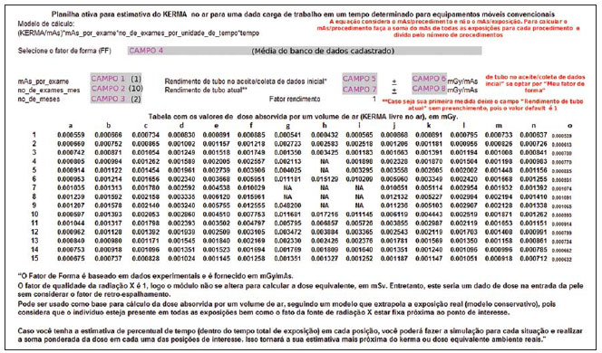 Figure 2. Data worksheet showing the way of searching registered data. The grey-marked fields are those where the user interacts with the system. 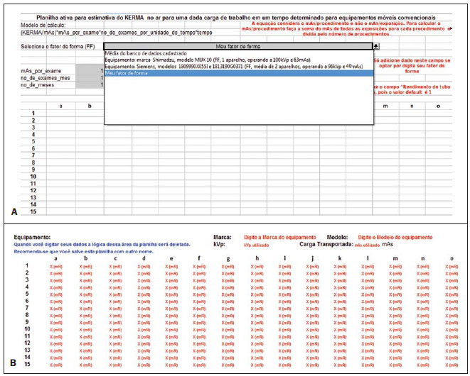 Figure 3. Selection of the customized mode (A) by means of the option "My shape factor", and (B) personalized data input area (fields with red letters). The above mentioned parameters serve as the basis for determining the kerma total at each point of interest on the mesh-grid. The ratio defined by equation 1 is applied to each point of the mesh-grid to build the final map presented on the "Table of absorbed dose values per air volume (air kerma free in air), in mGy". 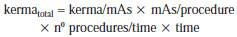 In order to initiate the utilization of the tool, the user must open the mobil_xr_ KERMAar_english.xls file. At this point, the user will visualize the Calculation_ worksheet (Planilha_de_cálculo) shown on Figure 2. After entering the mandatory basic data for the calculation in the fields 1, 2, 3, and 4 (Figure 2), the results will be automatically demonstrated on this same worksheet, on the "Table of absorbed dose values by air volume (kerma free in air), in mGy". The format selected for the presentation of data was a table comprising 15 columns (named "a" thru "o") and 15 lines (numbered from 1 thru 15). Each cell on this worksheet corresponds to a measurement point, with the distance between two consecutive measurement points being 30.0 cm. The mobile X-ray equipment was placed at the center of the field of interest, i.e., with the reference central beam located in the "h8" cell of the table of results. The cells shown on the table as NA ("non applicable") represent those cells where the measurements could not be performed either because that particular position was occupied by the equipment console or because the chest phantom was located in that position (being that a region which was exposed to the primary beam). The positioning of the mobile equipment's X-ray tube was defined in such a manner so the mobile equipment's console was always located in the map regions defined by lines "1" and "8", and columns "f" and "j". The toolkit allows the utilization of variation in the X -ay tube performance test results as a way to adjust the SFs to the X-ray tube performance variations in the different apparatuses or from same equipment as function of time. Thus, one can utilize the collected data in the service life of the equipment, without the need for new SF data collections for that same equipment. The X-ray tube performance data must be entered into fields 5, 6, 7 and 8 (Figure 2). At fields 5 and 6 the tube performance values as well as the respective standard deviations must be entered respectively for the reference data, i.e., the valid tube performance values for the SF data collection period. At fields 7 and 8, one enters the valid tube performance values in the period of interest for the calculation. Such a correction also serves the purpose of adjusting data for apparatuses of a same brand and model, when utilized at the same tube voltage as the data stored in the database. Limitations of the model implemented in the toolkit According to the proposed method, the presented results take into consideration the case where highest exposure is produced. Therefore the present method is conservative, and considers that all examinations were performed at the same position at the patient's bedside utilized as a reference for calculation. Although valid, this is an extremely conservative method for evaluating the situation in question. In truth, there is a distribution among the beds which has not been determined. It is suggested that, in cases where the frequency of examinations for each bed can be determined, the different possibilities be separately considered on the worksheet, with the kermatotal being determined by means of the sum of the participations of each ratio in the total of performed examinations, so that such normalization is considered in the total estimate of skin entrance kerma. It is important to note that the proposed method presents limitations; the most noticeable of them are the following: the need for verification of quality control tests performed on the mobile equipment in question, the need for the tube voltage to be similar to that utilized in the examinations, and the utilization of correction factors for the variation of the rate of kerma emitted by the X-ray generating equipment as it ages. Thus, in order to obtain the actual dose on the patients by means of the calculation, the data collection should be performed once in the whole mesh-grid, and SF corrections should be applied every year, based on the variation of the tube performance data for a same acceleration voltage. Once the X-ray generating equipment has passed all the quality control tests, i.e., it is in compliance with all Brazilian standards, particularly those regarding linearity of kerma response with mAs, it is possible to estimate the skin entrance kerma due to X-radiation scattered per examination, by multiplying the value on the data table by the value of mAs of the examination in the room. RESULTS Presentation of the toolkit In association with the proposed data collection, the developed toolkit demonstrates to be safe and appropriate, within the method limitations mentioned under "Material and Methods". Figure 2 illustrates an example of data input and the obtained result for the system internal database, where CAMPO 4 (field 4) "Selecione o fator de forma (FF)" (Select the shape factor (SF)) was defined by the option " Mean value for the registered database", and the remaining fields were defined as follows: CAMPO 1 (field 1) = "mAs_por_exame" (mAs_by_procedure) defined as 1 mAs; CAMPO 2 (field 2) = "no_de_exames_mes" (number of examinations per month), defined as 10 exams performed per month; and CAMPO 3 (field 3) = "no_de_exames_mes" (no_of_ procedures_month) defined as two-month hospital stay. Those are the mandatory data entries which must be defined by the user. The fields 5 and 6, regarding "tube performance at initial acceptance/data collection", are automatically filled if the user chooses to utilize data from apparatuses already registered in the tool. Such fields should only be filled out in case the user intends to utilize customized data which have not been recently collected, requiring correction (in case the utilized equipment presents changes in the tube performance test values). The fields regarding "Current tube performance" (fields 7 and 8) should only be filled out if the user intends to utilize such correction factor in the results. In case the user does not have the "Current tube performance" data or does not wish to utilize the correction factor, the field should not be filled out, and by default the utilized correction factor will be 1. The toolkit also allows the user to enter customized data for a given equipment (collected at his/her institution), provided the user selects the option "Meu Fator de Forma (FF)" (My Shape Factor (SF)) at CAMPO 4 (field 4) at "Selecione o Fator de Forma (FF)" (Select de shape factor (SF)), as shown on Figure 3A. Automatically, below the data output worksheet advises, a table for customized data entry will be exhibited (Figure 3B). The fields to be filled out are highlighted in red, identifying the information to be entered. The exposure data must be added at the mR unit, in the space reserved for data input, marked as X (mR), as shown on Figure 3B. The worksheet will automatically normalize in mAs (provided the field of transported load is informed) and will perform the calculations for the generation of results. It is important to notice that the data collection for building up the mesh-grid places considerable stress on the tube, and must be performed in different phases to avoid tube overheating. Along the development of the present study, the authors took, on average, 18 hours for collecting the data from each complete mesh-grid, with data from each quadrant being collected in different days. The authors wish to encourage users to send their SFs to be added to the tool, with the purpose of building up a large shared database. Users who wish to collaborate by adding data from their mobile apparatuses should, after collecting the data according to the method described on the above mentioned articles, send an e-mail to GESiC (ghoff.gesic@gmail.com) including the data worksheet comprising the normalized exposure data in mR/mAs, and the mobile equipment tracking data (make, model and other pertinent data), as well as the value for tube performance of the equipment which was valid in the data collection period. The toolkit, in English, as well as all information required to participate by including user data in the toolkit's database, and contact information on the authors of the present study are available for download at http://www.gesic.com.br/conteudo/equipamento_movel_planilha.html. Toolkit applications: study of actual cases Generally, the toolkit utilizes SFs data to initiate the assessment of dosimetric quantities. The charts presented on Figure 4 show the isoexposure curves which constitute the data base of the toolkit developed in the present study. The internal lines, close to the X-radiation generating equipment present the highest exposure values, while the external lines present the lowest values. One observes a common tendency among the lines to circumvent the central 77 Hoff G et al. Evaluation of radioprotection in areas of inpatients care beam area. Additionally, the curves shapes on Figure 4A and 4B are relatively rectangular and similar. The exception is the chart on Figure 4C, which presents a distortion which makes the shape triangular. 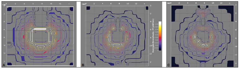 Figure 4. Isoexposure maps in mR/mAs generated for each evaluated equipment: Shimadzu (A), Siemens model 1809990X055I (B) and Siemens model 1813190G0371 (C). The scale of dimensions X and Y is 18.8:1. The color scale remains constant for all the charts included in this figure. Case study 1 Protection for inpatients on beds located in areas where mobile Xradiation apparatuses are utilized. As the application of radiological protection of patients is considered, it is important to highlight that there are different areas in which mobile X-radiation generating apparatuses are utilized in hospitals. Usually, the distance between the central axis of the radiation beam and the individual of interest is not determined by regulations and as examples one can mention pediatric emergency departments and both neonatal and adult ICUs. The Brazilian Standard RDC 50(18) recommends a distance between beds corresponding to 0.8 m for anesthesia recovery areas and 2.0 m for collective work areas. Mandatory distances for neonatal areas are not specified. Areas for which there are no specification, or where it is not possible to maintain the minimum 2.0 m distance between beds or pediatric incubators, may be troublesome in the evaluation of radiological protection. In such cases, the results of the present study allow the definition of safe distances for hospital inpatients, whenever moving the bed is at all possible, or allows the estimation of entrance skin air kerma in patients for assessment of exposure levels. Tables 1 and 2 show results calculated by the toolkit with basis on the collected experimental data for the validation of such toolkit for applications of patients' radiological protection. 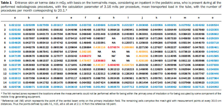 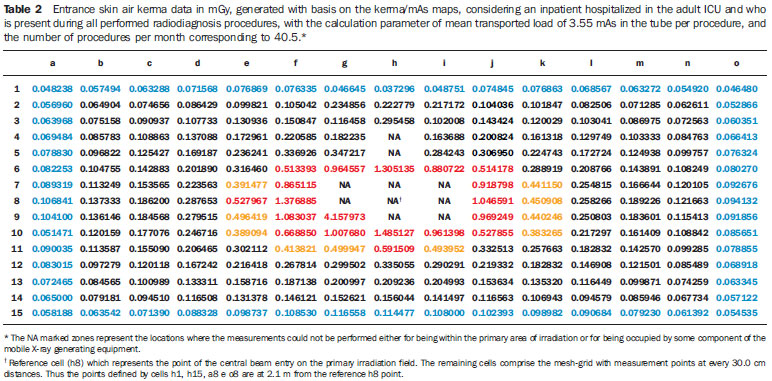 Tables 1 and 2 highlight in red the data equal or above the level determined for radiation free areas. Data in yellow show values below the level determined for radiation free areas, but due to possible fluctuations and variations in apparatuses response, such data are likely to reach the radiation thresholds. Data in blue define the contour of the collection area, with data being collected at the greatest distances. Based on the Brazilian regulations, stretchers/ beds/incubators should be positioned at distances > 2.0 m. In those cases where this is not possible, the results of the present study can be useful in the determination of safe areas to which stretchers/beds/incubators could be moved before X-radiation is utilized. In the case of the apparatuses evaluated in the present study, the safety distance would be above 70.0 cm from the central beam of the primary irradiation field and the edge of the stretcher/bed/incubator. The data were calculated considering one patient who has been hospitalized over a one-year period and, during the performance of radiological examinations, always remains beside the bed where the procedures are being performed. Case study 2 Protection for non-occupationally exposed individuals working in hospitalization areas where mobile X-radiation generating apparatuses are utilized. Another form of utilization of the toolkit is for protecting workers in areas where mobile apparatuses are utilized. The Brazilian regulations require that workers in areas where radiological diagnostic procedures are performed with mobile equipment, be positioned at least 2.0 m away from the central beam of the primary irradiation field. In practice, it is requested that workers to remain in the room only in those cases where their presence is indispensable. Tables 3 and 4 demonstrate the entrance skin air kerma considering the mean value for the three apparatuses evaluated in the present study and one year of work (11 months of activities performed in hospital bed areas) for two different units (pediatric and adult ICU). Such data can be utilized to define the risk associated with additional irradiation as well as to verify the possible additional entrance skin exposure caused by scattered radiation. 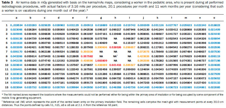 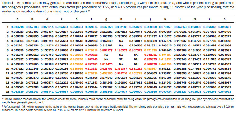 Tables 3 and 4 where data equal or above the determined level for radiation free areas are highlighted in red. Data in yellow demonstrate the values that are below such level but, considering possible fluctuations and variations in the apparatuses response, are likely to reach the radiation thresholds. Data in blue mark the contour of the collection area, with data being collected at the greatest distances. The tables show that, for the apparatuses evaluated in the present study, the safety distance would be above 70.0 cm between the central beam of the primary irradiation field and the edge of the stretcher/ bed/incubator. The data were calculated for a non-occupationally exposed individual, working over 11 months of the year. DISCUSSION The developed calculation tool, associated with the proposed data collection method, demonstrated to be appropriate and traceable, provided that the mobile Xray equipment in question is operating within the quality control test compliance parameters. Such a worksheet may be customized, allowing the input of user's specific equipment data. For the performance of the measurements, a non-anthropomorphic phantom which can be easily built and an ionization chamber calibrated for secondary beams are necessary. During the development of the toolkit, the authors have opted for making available the entry of the institution's characterization data at the header, as well as the possibility of kerma measurements data input by the user, given the peculiarities and particularities of each institution and applied techniques(1113). From the authors' point of view, this makes the toolkit nimble and adaptable for the application of the proposed method in different mobile equipment use areas. The Portaria 453/98(1) defines as radiation free areas those which are exempted from special radiologic protection control, where the ambient dose equivalent must be lower than 0.5 mSv/year. At Tables 1 and 2 data, which were the basis for case study 1, which considers one patient present at all radiological procedures performed with mobile apparatuses in the pediatric and adult ICU areas, one observes four measurement points (pediatric area) and 19 measurement points (adult ICU area) above the standard limit (points highlighted in red) with values above the recommended level for radiation free areas. Such points are located 30.0 cm (pediatric area) and 60.0 cm (adult ICU) distant from the central beam of the primary irradiation field, corresponding to an individual leaning against the stretcher/bed/incubator of the irradiated patient. The points highlighted in yellow represent those points with threshold data, i.e., points that could be in the limit area of the definition of radiation free areas, given the variations in experimental data. For the points located at 2.1 m, all the measurements are below the recommended maximum level for ambient dose equivalent in radiation free areas, with most of those points presenting values lower than 12% of the limit, and all the values below 20% of the limit for radiation free areas. Observing the data on Tables 3 and 4, which consider a worker present at all performed radiological procedures using mobile apparatuses in the pediatric and adult ICU areas, the worst case (adult ICU) shows that 15 points (in red) are above the recommended level for radiation free areas, all of such points located within a radius of 60.0 cm from the central beam of the primary irradiation field, corresponding to a person leaning against the patients bed. The points highlighted in yellow represent threshold points, i.e., points that could be in the threshold area for definition of a radiation free area, given variations in experimental data. For the points located at 2.1 m, all measurements are below the maximum recommended value for ambient dose equivalent in radiation free areas, with all points presenting values lower than 15% of such limit value. Considering safety and radiological protection issues which are common to the areas where radiodiagnosis procedures are performed with mobile apparatuses, it is important to take the definition of radiation free areas into consideration. Such a definition, according to the Portaria 453/98, is "the area exempted from special radiological protection controls". Thus, based on the experimental data from the present study, areas which are above 2.0 m from the central axis of the primary beam are safe, with no need for the utilization of dosimeters or any other type of monitoring devices or shielding. In truth, for individuals who remain at 2.0 m from the center of the primary irradiation field, the data demonstrate values always below 20% (for the worst evaluated case) of the defined maximum value for ambient dose used for the definition of radiation free areas. Thus, it can be affirmed that, for the evaluated apparatuses and calculation parameters, it is safe to remain in areas distant more than 2.0 m from the center of the primary irradiation field, being such areas considered as being radiation free according to the definitions established by the Portaria 453/98(1). In cases where it is impossible to move the patients to such areas, one can, with basis on the curves, define safe regions, positioning the mobile equipment in such a manner that patients who cannot be moved to the safe areas remain out of the area defined by data in red and yellow on Tables 1, 2, 3 and 4, thus minimizing the radiation exposure. However, one observes that the data in the present study are based on the mean value of exposure data in mAs collected from different apparatuses and that each one of those apparatuses has its own peculiarities. The toolkit allows such data to be utilized for apparatuses included in the database. However, considering the peculiarities of the mobile apparatuses utilized in hospitals, it is suggested that, whenever possible, the data on the exposure meshgrid in mAs be collected for each mobile equipment in the hospital. Thus the evaluation will present data that are closer to the reality in the particular hospital or clinic. In case that is not possible, the worksheet in the present study presents an acceptable approximation of the curves for apparatuses in general, provided that the added calculation parameters are based on the actual conditions of the particular hospital or clinic. The toolkit proposed by the present study allows the customization of the data obtained in a hospital or clinic and its use for the definition of the risk associated with the entrance skin exposure. In order to transform such exposure into a dose on a certain organ or tissue and/or into a whole body dose, it is necessary to utilize a coefficient for conversion of exposure into dose. Such factors for conversion of kerma or exposure into effective dose are well defined for primary radiation, but are yet to be calculated for exposures originating from secondary radiation. One suggests the determination of such factors in order to complete the analysis. CONCLUSIONS AND SUGGESTIONS The developed toolkit is user-friendly and its utilization does not require coding skills. The method presented in this study, associated with the utilization of the developed toolkit in Excel®, and utilizing the tube performance data from the equipment utilized in a hospital, allows the calculation of the ambient dose or the entrance skin dose on patients (without considering retroscattering). The results provided by the developed toolkit may be directly utilized to evaluate the safety of inpatients who are hospitalized in areas where the dimensions/distances between the beds are not legally defined, or the distances between the beds are lower than 2.0 m. Additionally, the dose maps may be utilized for assessment of changes in the ambient dose on account of changes in workload of the location. With the additional collection of exposure data for other acceleration voltages, the toolkit may also be useful in the assessment of shape factors and, consequently, in the assessment of ambient doses with the changes in radiographic technique. This allows the evaluation of the impact of the optimization of the radiographic technique on the radiological protection of inpatients and workers in areas where mobile apparatuses are utilized. In addition, the proposed method, in association with the utilization of the developed toolkit (Excel® worksheet), may be applied to optimize the dose to patients and to evaluate the ambient dose in all areas where mobile apparatuses are utilized in the hospital/clinic, allowing the follow-up of such dosimetric parameters and evaluating the possibility of optimization of the radiological protection. It is suggested that additional risks associated with such exposure condition are evaluated. For this purpose, it is of particular importance to determine the effective doses on patients that are within or at the threshold of the controlled area. Patients who are outside the controlled area may be evaluated, but one should remember that they are in an area characterized as a radiation free area. In order to perform such calculation, it is necessary to determine the factors for conversion of kerma into effective dose for scattered radiation. Thus, the kerma data from the mesh-grid can be converted into effective dose, especially in cases where the beds are within the 2.0 m area, allowing the evaluation of the risk associated with that additional exposure. Such data would constitute the experimental basis for the semi empirical model proposed in the present study, in which retroscattering and coefficients for conversion of kerma into effective dose (cceffective) and into absorbed dose (ccabsorbed) are considered as theoretical participating entities, for geometry and considerations on the utilized spectrum. Equations 2 and 3 show the proposed semi-empirical models, where WT represents the radiation weighting factor. 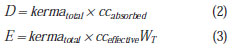 The ccabsorbed and cceffective coefficients will be evaluated in the future by means of computational simulation data. As the radiation weighting factor corresponds to 1 for X-radiation, it was not shown on equation 2. The cceffective coefficient represents the summation of all ccabsorbed for organs and tissues in the body of interest. It is estimated that this model presents effective results for risk assessment in patients located at less than 1.0 m from the central radiation beam, for those cases where such patients cannot be moved from the location. The GESiC is initiating the simulations for the determination of the retroscattering factors ccabsorbed and cceffective, considering the scattered spectrum for the geometry described in the present study. REFERENCES 1. Kramer R, Khoury HJ, Vieira JW. CALDose_X a software tool for the assessment of organ and tissue absorbed doses, effective dose and cancer risks in diagnostic radiology. Phys Med Biol. 2008;53:643759. 2. Standard dosimetry. Radar software: Mirdose and Olinda/EXM. [acessado em 26 de outubro de 2011]. Disponível em: http://www.doseinforadar.com/RADARSoft.html#MDOL. 3. Labcity. Echo® dose-response software. [acessado em 26 de outubro de 2011]. Disponível em: http://www.labcyte.comEcho%C2%AE_DoseResponse_Software/Default.288.html 4. Rad Pro Calculators. Gamma emitter point source dose-rate to activity and shielding calculations (in air). [acessado em 26 de outubro de 2011]. Disponível em: http://www.radprocalculator.com/Gamma.aspx 5. International Commission on Radiological Protection. Radiological protection in medicine. ICRP Publication 105. Ann ICRP. 2007;37(6). 6. International Commission on Radiological Protection. The optimization of radiological protection broadening the process. ICRP Publication 101b. Ann ICRP. 2006;36(3). 7. United Nations Scientific Committee on the Effects of Atomic Radiation. UNSCEAR 2000 Report to the General Assembly, with scientific annexes. Annex A: Dose assessment methodologies. Vol 1,p. 2982;2000. 8. United Nations Scientific Committee on the Effects of Atomic Radiation. UNSCEAR 2000 Report to the General Assembly, with scientific annexes. Annex G: Biological effects at low radiation doses. Vol 2,p. 73175;2000. 9. Brasil. Ministério da Saúde. Agência Nacional de Vigilância Sanitária. Diretrizes de proteção radiológica em radiodiagnóstico médico e odontológico. Portaria nº 453/98. Brasília, DF: Diário Oficial da União, 2 de junho de 1998. 10. Brasil. Ministério da Saúde. Agência Nacional de Vigilância Sanitária. Resolução 1016. Brasília, DF: Diário Oficial da União, 5 de abril de 2006. 11. Brasil. Ministério da Saúde. Agência Nacional de Vigilância Sanitária. Radiodiagnóstico médico: desempenho de equipamentos e segurança. Brasília, DF; Ministério da Saúde; 2005. 12. National Council on Radiation Protection & Measurement. NCRP Report No. 107. Implementation of the principle of As Low As Reasonable Achievable (ALARA) for medical and dental personnel. Bethesda, MD: National Council on Radiation Protection & Measurements; 1990. 13. American Association of Physicists in Medicine. Standardized methods for measuring diagnostic X-ray exposures. AAPM Report no. 31. New York, NY: American Association of Physicists in Medicine; 1990. 14. American College of Radiology. ACR practice guideline for diagnostic reference levels in medical X-ray imaging (Revised 2008). Reston, VA: American College of Radiology; 2008. 15. Compagnone G, Pagan L, Bergamini C. Comparison of six phantoms for entrance skin dose evaluation in 11 standard X-ray examinations. J Appl Clin Med Phys. 2005;6:10113. 16. Hoff G, Andrade JRM, Fisher ACFS, et al. Mapeamento de curvas de isoexposição geradas por equipamentos de radiodiagnostico móveis convencionais e dose em pacientes hospitalizados. In: II Congresso Brasileiro de Proteção Radiológica. Recife, PE, Brasil; 2011. 17. Bacelar A, Andrade JRM, Fisher ACFS, et al. Mapeamento de curvas de isoexposição para avaliação de equivalente de dose ambiente para equipamentos móveis de radiodiagnóstico. In: II Congresso Brasileiro de Proteção Radiológica. Recife, PE, Brasil; 2011. 18. Brasil. Ministério da Saúde. Agência Nacional de Vigilância Sanitária. Resolução RDC nº 50, de 21 de fevereiro de 2002. Dispõe sobre o Regulamento Técnico para planejamento, programação, elaboração e avaliação de projetos físicos de estabelecimentos assistenciais de saúde. Brasília, DF: Diário Oficial da União, 20 de março de 2002. 1. PhD, Full Professor, Pontifícia Universidade Católica do Rio Grande do Sul (PUCRS), Porto Alegre, RS, Brazil. 2. Bachelor of Physics, Physicist, Service of Medical Physics and Radioprotection, Hospital de Clínicas de Porto Alegre (HCPA), Porto Alegre, RS, Brazil. 3. Graduate Student, Course of Medical Physics, Pontifícia Universidade Católica do Rio Grande do Sul (PUCRS), Porto Alegre, RS, Brazil. 4. Master, Head of Service of Medical Physics and Radioprotection, Hospital de Clínicas de Porto Alegre (HCPA), Porto Alegre, RS, Brazil. Mailing Address: Dra. Gabriela Hoff Avenida Ipiranga, 6681, Prédio 10, Sala 207, Partenon Porto Alegre, RS, Brazil, 91629- 900 E-mail: ghoff.gesic@gmail.com Received August 26, 2011. Accepted after revision February 23, 2012. Study developed with the Group of Experimentation and Computational Simulations in Medical Physics, Pontifícia Universidade Católica do Rio Grande do Sul (PUCRS), Porto Alegre, RS, Brazil. |
|
Av. Paulista, 37 - 7° andar - Conj. 71 - CEP 01311-902 - São Paulo - SP - Brazil - Phone: (11) 3372-4544 - Fax: (11) 3372-4554