Radiologia Brasileira - Publicação Científica Oficial do Colégio Brasileiro de Radiologia
AMB - Associação Médica Brasileira CNA - Comissão Nacional de Acreditação
 Vol. 40 nº 1 - Jan. /Feb. of 2007
|
ORIGINAL ARTICLE
|
|
The relevance of quality control in services of hemodynamics and interventional cardiology |
|
|
Autho(rs): Eara de Souza Luz, Lucía Viviana Canevaro, Nadya Maria Prado Damasceno Ferreira, Julio Eduardo Campos |
|
|
Keywords: Interventional radiology, Hemodynamics, Quality control |
|
|
Abstract:
IM.Sc. in Nuclear Engineering, Instituto Militar de Engenharia
INTRODUCTION Interventional radiology involves diagnostic and/ortherapeutical interventions guided by means of percutaneous orother access, and usually performed under local anesthesia and/orsedation, using a fluoroscopic image to localize a lesion ortreatment site, the fluoroscopy plying the main role ofmonitoring the procedure, controlling and documenting thetherapy(1). It is one of the radiodiagnosismethods which give patients highest radiation doses, and wherethe exposure to radiation is more critical for the practitioners.The percutaneous access is performed by means of a guidedcatheter inserted by the physician. The catheter insertion up tothe treatment site, as well as the whole diagnostic andtherapeutical procedure, is performed under fluoroscopy, whoseimages are displayed on monitors both inside and out of the room.Because of the need for iodine contrast injection, and their highdegree of complexity, the procedures require the support ofassistant physicians, technicians and nurses to be performed. Fora better visualization of the site to be investigated, it ispossible to change the x-ray beam angle of incidence around thepatient, sometimes increasing the level of radiation exposure forthe operator and assistants near the x-ray equipment.Additionally to the relative positioning of the x-ray tube, theradiation exposure is proportional to the technique utilizedduring the whole procedure, and parameters like voltage (kV),amperage (mA), dosing rates, the fluoroscopy times, amongothers. On the other hand, in interventional radiology, attention mustbe paid to the imaging quality, considering the reduced calibersand different densities of structures and tissues to bestudied. So, the optimization of the practices in interventionalradiology is a critical aspect that should not be disregarded.Quality control procedures constitute a tool in the process ofoptimization of the radiological protection in the practices, bymeans of monitoring of the different parameters influencing theequipment performance, the radiation doses both for patients andpractitioners, and the images quality. The quality control allowsthe monitoring and maintenance of the quality necessary fordiagnostic or therapeutical purposes of the interventionalprocedures in question(2,3). The Brazilianlegislation concerning radiological protections in radiodiagnosis— Ministry of Health Order (Portaria) no.453/98(4) — establishes few requirementsregarding quality control in interventional radiology. In Aprilof 2003, the Agência Nacional de VigilânciaSanitária (National Agency for Sanitary Vigilance)published the Resolution no. 64(5) with somerecommendations about procedures of quality control fordiagnostic services, including some tests in fluoroscopy.Performing periodical testing is not a routine practice in theBrazilian hospitals yet. The objective of the present study was to evaluate the performance of a x-ray equipment utilized in interventional radiology, applying some quality control tests.
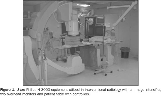
MATERIALS AND METHODS The present study has been developed in a Philips Integris H3000 model fluoroscopic equipment (Figure 1) installed in a hemodynamics service of a large hospital in Rio de Janeiro, RJ, Brazil. The equipment operates in the following modes: continuous low and normal, and pulsed high, 13 cm, 18 cm and 23 cm magnification modes (also called lens or zoom mode), digital cine image acquisition, and exposure control. The fluoroscopy modes determine the dosing rates delivered by the x-ray beams. So, for a single exposure time, the high mode should deliver to the patient a higher dose than the low and normal modes. The magnification modes allow an increase in spatial resolution of images of the region to be studied. It is important to note that the lower the magnification mode, the higher the patient dose to allow a same image quality. The values of 13 cm, 18 cm and 23 cm represent the diameter of the image intensifier input screen utilized.
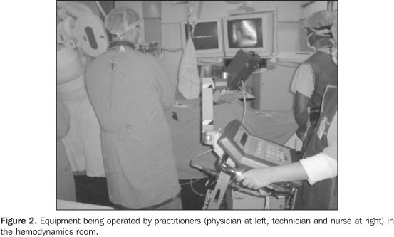
In equipment evaluated in the present study, the controllers for the arc movements and distance between the x-ray tube and the images intensifier are coupled with the table. The equipment has two video monitors inside the room for visualizing the procedures (Figure 2). The video monitor at left is utilized for images freezing, while the video monitor at right displays real time image during the procedure. For the procedures optimization, the quality of the images must meet the quality criteria according to the objective to be reached.
One of the ways to estimate the radiation dose delivered tothe patients is measuring the amount of energy deposited per massunit, denominated "air kerma", expressed in milliGray (mGy). Duethe dynamic nature of this procedure, in fluoroscopy, it is moreappropriate to measure the "air kerma rate" (in units of mGy/min)than simply the air kerma. Dosimetric tests were performed to evaluate the air kerma ratein the patient's skin entrance, in the image intensifier input,and image quality test for evaluating high- and low-contrastspatial resolutions and distortion. Also the half-value layer(HVL) was evaluated. Measurements of skin entrance and image intensifier inputair kerma rates The measurement of skin entrance and image intensifier inputair kerma rates should be performed on an annual basis and/orafter equipment repairs, under normal operational conditions. Themeasurement of the image intensifier input air kerma rate yieldsan estimate of x-ray equipment performance. A Radcal dosimetric system consisting of a 9015 electrometer and a 10X5-60cc ionization chamber was utilized, with the ionization chamber positioned towards the x-ray beam. The reading is made by the electrometer. For simulating the presence of a patient, a 1mm-thick copper plate was utilized. The plate, as well as the patient, attenuates the x-ray beam (Figure 3). The skin entrance air kerma rate was measured for 18 cm and 23 cm magnifying modes (image intensifier diameter) which are the most utilized in procedures of this hemodynamics service. The x-ray tube was positioned at 100 cm from the image intensifier, with the ionization chamber at 30 cm from the image intensifier input, and 1 cm above the table, within the radiation field. The copper plate was placed over the ionization chamber (Figure 3).
For evaluating the image intensifier input air kerma rate, the ionization chamber was fixed in the intensifier input, and the x-ray tube was positioned at 85 cm from the image intensifier. The copper plate was placed on the examination table for simulating the patient. Exposures were performed registering the air kerma rate in mGy/min measured by the ionization chamber in low, normal and high fluoroscopic modes, as well as the kilovoltage (kVp) and amperage utilized for 18 cm and 23 cm magnification modes (Figure 4).
Evaluation of high-contrast spatial resolution and low-contrast discrimination The estimation of high- and low-contrast resolutions wasperformed with the aid of test objects developed by University ofLeeds for semiquantitatively analyzing x-ray imagesquality(6,7). The test objects bear details ofdifferent materials and thicknesses inside. For the testing, eachtest object is fixed to the image intensifier input screen. It isrecommended that tests are ran at each half-year or every timethe equipment is serviced. The high-contrast spatial resolution is evaluated in terms of line pairs per millimeter (lp/mm), discriminating alternating black and white line pairs into groups of different spatial frequencies on the image displayed on the monitor screen. The low-contrast resolution is evaluated in terms of percentage of contrast between circles of different densities (details) and their background on the image displayed on the monitor screen or image register system. Figure 5 shows the image of a Leeds TOR (TVF) test object.
For determining the high-contrast resolution of the imagedisplayed on the monitor screen of the x-ray equipment inquestion, one has identified the group of line pairs where twolines can be separately identified. For determining the number oflp/mm that the images system can resolve, the Leeds test objectmanual includes a table of equivalences between the groupidentified on the image and the correspondent number oflp/mm. The low-contrast resolution evaluation consists of the counting of visible circles (those differentiated from the background) on the image displayed on the monitor screen. For the low-contrast resolution, the Leeds test objects manual(6,7) includes a table with the contrast degree as a function of the number of circles identified on the image, and suggests a 4% value as a lower acceptance threshold. The results were compared with those established by the order (Portaria) 453 (Table 1). However, it is important to note that the Order (Portaria) 453/98 generalizes the recommendations for a conventional fluoroscopic system, but acceptable thresholds should be defined by the physicist-physician responsible by the quality control for each x-ray equipment, considering the equipment specific application and the requirements of each interventional technique utilized (cardiology, vascular medicine, neuroradiology, etc.).
Distortion This test is aimed at determining whether the imaging system introduces geometrical distortion on images displayed on the available monitor screens. In case this distortion exists, the Leeds TO M1 test object allows the quantification of the distortion degree. If the distortion is significant, the image on the monitor screen, mainly the internal monitor in the hemodynamics room, may lead to misinterpretation during the procedure. The Leeds TO M1 is a wire grid (radiopaque material) test object that allows the observation of a square matrix image on the monitor (Figure 6), where the distances between vertical and horizontal lines are uniform and known.
The distortion on the internal monitor of the hemodynamics room was evaluated. The test was performed with the test object fixed to the images intensifier input screen so that the central square was positioned closer to the irradiation center. On an image without geometric distortion, all the squares should present the same dimensions, corresponding to perfect squares. The evaluation is aimed at identifying the largest visible square matrix (n x n squares) on the image. Then, the main and secondary diagonals of the largest square matrix were measured with a ruler, as well as those of the squares in the center and extreme points of the matrix (lower left and right, and upper left and right). A square region (seven squares on the horizontal plane, and seven on the vertical plane) was evaluated. The distortion was calculated in the region where the diagonals of the extreme points squares are larger in length. Based on the measured values, the image distortion on the monitor was determined by means of equation 1:
where: Dc is the central square diagonal; nis the number of complete squares utilized for representing thediagonal of the region with higher distortion; and Dmis the sum of the squares diagonals of the diagonal with higherdistortion. Half-value layer evaluation HVL is defined as the aluminum (or equivalent material) filterthickness that must be placed on the x-ray beam output port toreduce the intensity at half. The HVL is an essential parameterfor characterizing the beam quality, and based on this value, itis possible to determine the total x-ray tube filtration. Asalready known, aluminum (Al) filters are placed to attenuatelow-energy photons which do not contribute to the imagesformation, but rather to the dose delivered to the patient. Theminimum total filtration of a diagnostic x-ray equipment musthave is at least 2.5 mmAl(4). The objective ofthe HVL measurement is to evaluate whether the x-ray tube has anadequate filtration. This test must be performed once a year andafter repairs(4). The device utilized in this test was a Radcal 10X5-60 ionization chamber coupled with an electrometer, Al filters and a tape measure. The measurements were performed for an 18 cm magnification in the normal scopy mode. The ionization chamber was positioned above the table, under the x-ray beam, at a 45 cm distance from the focal point. The distance between the focal point and the image intensifier was 101 cm. The Al filters were placed between the ionization chamber and the image intensifier up to achieving a tube voltage near 50 kVp. Aiming at keeping a constant irradiated thickness, all the filters remained positioned towards the x-ray beam during this test for not modifying the automatic exposure control settings. The first exposure was performed with the filters positioned between the chamber and the images intensifier (non-attenuated beam). During the test, the filters were displaced one by one, between the x-ray tube and the ionization chamber (attenuated beam). For each displacement 1 min exposures were performed, and the air kerma rate measured. This procedure was repeated up to a value lower than half the value of the first reading was achieved. The HVL value was found by means of equation 2:
where: L0 is the average of the initial exposurereadings; La is the exposure reading immediatelysuperior to L0/2; Lb is the exposurereading immediately inferior to L0/2; Xa isthe Al thickness corresponding to the La reading;Xb is the Al thickness corresponding to theLb reading. Aiming at knowing the HVL value for 50kVp, an interpolation was performed with basis on the HVL table included in the Order (Portaria) 453/98(4).
RESULTS AND DISCUSSION Measurement of skin entrance and image intensifier inputair kerma rate The results of the measurements of skin entrance and image intensifier input air kerma rates performed in the x-ray equipment utilized in the present study are included in Table 1. The skin entrance air kerma rate resulted lower than those established by Order (Portaria) 453/98(4). In the present study, the skin entrance and image intensifierinput air kerma rates measured in high mode were lower than thosein the normal mode, although the reverse result was expected.However, we have observed that while in the high mode the beam ispulsed, in the normal mode the fluoroscopy is continuous. Thepulsed fluoroscopy contributes for minimizing the exposure, butthe diagnostic image quality is lower. Typically, in the highmode, the air kerma rate is high, allowing a better imagesquality, a feature some times required by the interventionalprocedure, when better resolution and contrast of certain regionsare necessary. This characteristic was not observed in themeasured skin entrance air kerma rates, a fact suggesting thatthe air kerma rate in the high mode was changed in the x-rayequipment, probably to reduce the dose delivered to the patient.So, the utilization of the high mode has lost its function. Both for the high and normal modes, a magnification variation(from 18 cm to 23 cm) did not present a significant influence onthe rates measured, within the uncertainties associated with themeasurements. The air kerma rate also is high during the utilization of theequipment in the images acquisition (cine) mode, as a function ofthe need for high quality images. Evaluation of the high-contrast spatial resolution, low-contrast discrimination, anddistortion The tests results for high-contrast resolution are shown on Table 2. Aiming at guaranteeing a good diagnosis in interventional radiology procedures performed in hemodynamics services, a high-contrast resolution is necessary to identify arteries, veins and lesions to be investigated, mainly for coronary procedures where the investigated and treated structures present low caliber. The Order (Portaria) 453/98(4) recommends a high-contrast resolution value expressed in lp/mm > 1.4 lp/mm for the 15–18 cm magnification mode, and = 1.0 lp/mm for the 23–25 cm magnification mode. However, the values found in this test, on the internal hemodynamics room monitor, resulted lower than the recommended ones. This suggests that there may be anatomical details of difficult visualization on images observed on the monitor screen, inducing the physician to submit the patient to longer exposure times for acquisition of a higher number of images.
On Tables 1 and 2, it is possible to observe that, in spite of the skin entrance air kerma rate being higher in the normal mode than in the high mode, there was no improvement in the image quality (high- and low-contrast resolutions) on the internal monitor. For low-contrast, a resolution between 1% and 4% is recommended(1,4–7). The values found by the present study present an acceptable low-contrast resolution, according to Table 2. Generally, the external monitor presented a higher qualitythan the internal one. It is important to note that the imagequality is strictly related to the final medical-diagnosticobjective of the procedure. In the distortion test, the evaluated monitor presented 5.1% distortion, lower than the 10% value recommended by the Leeds test objects manual(7). The results of the measurements are shown on Table 3, and calculations were made for the main diagonal, and with the squares of the left upper and right lower corners, employing the equation 1.
Half-value layer Values found in the HVL evaluation are shown on Table 4. The value resulting from the HVL calculated by means of equation 2 was 2.0 ± 0.1 mmAl, for a 50 kV voltage, with a reference value of 1.7 mmAl(4). For this value of HVL and voltage, the total filtration of this equipment resulted in 3.5 mmAl(8). The useful beam HVL value should not be lower than 2.5 mmAl.
CONCLUSIONS The results of the present study regarding dosimetricmeasurements (skin entrance and image intensifier input air kermarates) demonstrated the relevance of a periodical evaluation bymeans of quality control tests, allowing the monitoring of theequipment performance, detection of anomalies or operationalproblems, as well as an estimation of workers and patientsradiation exposure levels. In the same way, the results regarding images quality suggestthe necessity of a review of the images acquisition system of thefluoroscopic equipment. The periodical testing provides concretedata which can lead to an improvement in the image quality, sincethese data allow the identification of possible degradation ofthe imaging system along time. This evaluation is particularlysignificant on the monitor screen localized inside theexamination room, which is indispensable for the dynamic andreal-time follow-up of the procedure. The quality control is a tool in the implementation ofradiological protection measures for every individual involved ininterventional procedures, as well as other measures associatedwith prioritary aspects of equipment maintenance and achievementof an image quality sufficient to reach the required diagnosticresults. The physicist-physician interaction with the medicalprofessionals is essential for him to interpret his necessitiesallowing a safe work and accurate diagnosis. The consciousness ofphysicians and technicians on this aspect is extremely important,as well as an adequate training of every professional involved ininterventional radiology procedures. This is part of the work developed by the physicist-physician of the service, who must effectively participate in the specialists staff of a hospital, according to requirements of the Brazilian legislation and good practices recommendations associated with radiation.
REFERENCES 1. International Commission on Radiological Protection. Avoidance of radiation injuries from medical interventional procedures. ICRP Publication 85. Oxford: Pergamon Press, 2000. [ ] 2. Williams JR. The interdependence of staff and patient doses in interventional radiology. Br J Radiol 1997;70:498–503. [ ] 3. Faulkner K. Radiation protection in interventional radiology. Br J Radiol 1997;70:325–326. [ ] 4. Brasil. Ministério da Saúde. Diretrizes de proteção radiológica em radiodiagnóstico médico e odontológico. Portaria nº 453. Brasília: Diário oficial da União, 1/6/1998. [ ] 5. Brasil. Agência Nacional de Vigilância Sanitária. Guia de procedimentos para segurança e qualidade de imagem em radiodiagnóstico médico. Resolução nº 64, de 4 de abril de 2003. [ ] 6. Products of fluoroscopy. 2004 [cited 2004 Feb 21]. Available from: www.leedstestobjects.com [ ] 7. Cowen AR, Clarke OF, Coleman NJ, Craven DM, McArdle S, Hay GA. Leed x-ray test objects – instruction manual. Leeds LS1 3 EX, 1992. [ ] 8. International Commission on Radiological Protection. Protection of the patient in diagnostic radiology. ICRP Publication 34. Oxford: Pergamon Press, 1982. [ ]
Received February 17, 2006.
* Study developed at Instituto Militar de Engenharia and Instituto de Radioproteção e Dosimetria – Comissão Nacional de Energia Nuclear, Rio de Janeiro, RJ, Brazil. |
|

Av. Paulista, 37 - 7° andar - Conj. 71 - CEP 01311-902 - São Paulo - SP - Brazil - Phone: (11) 3372-4544 - Fax: (11) 3372-4554