Radiologia Brasileira - Publicação Científica Oficial do Colégio Brasileiro de Radiologia
AMB - Associação Médica Brasileira CNA - Comissão Nacional de Acreditação
 Vol. 46 nº 6 - Nov. / Dec. of 2013
|
ORIGINAL ARTICLE
|
|
Doses monitoring in radiology: calibration of air kerma-area product (PKA) meters |
|
|
Autho(rs): Ricardo Andrade Terini1; Maria Carolina de Santana Campelo2; José Neres de Almeida Jr.3; Silvio Bruni Herdade4; Marco Aurélio Guedes Pereira5 |
|
|
Keywords: Kerma; Meters; Calibration; Dosimetry; Radiology; X-rays. |
|
|
Abstract: INTRODUCTION
When radiosurgical or radiological procedures are performed, it is of utmost importance to utilize techniques that ensure the best image quality, contributing for the correct diagnosis or for the accuracy of surgical procedures. At the same time, however, it is necessary to monitor the radiation dose delivered to the patient in order to avoid immediate and future risks induced by the radiological procedures(1). By means of a kerma-area product (PKA) meter or a dose-area product (DAP) meter(2), it is possible to perform an evaluation of the air kerma integrated over the area to be irradiated, as well as, based on appropriate conversion factors(3,4), to estimate the effective dose or energy transmitted to the patient quantities, related to the risk caused by radiation. In Brazil, although there is no regulation enforcing the utilization of such devices, it is common to utilize imported x-ray emitting apparatuses equipped with a PKA meter coupled after the collimator of the x-ray tube, which may be either fixed or detachable. During the procedure, such device provides the PKA values with which the technicians and physicians have to deal with. Other systems estimate the values for PKA based on the equipment operational parameters. Thus, the correct evaluation of such readings is of utmost importance in order to ensure appropriate protection against radiation, both for the patient and the technical/medical team, which are subjected to scattered or even direct radiation during the procedures. The kerma-area product The quantity PKA, expressed in Gy.m2, is defined(5) as the integral of air kerma (Ka) over an area A, in an area (dxdy) of a plane perpendicular to the central axis of the x-ray beam, multiplied by the area A of the beam in the same plane (equation 1): PKA = ∫A Ka(x,y) dxdy (1) Its main advantage is that its value, by definition, is independent from the distance to the tube focus (because, for a given solid angle, the Ka value is proportional to the inverse square of the distance, and the beam area varies with the square of the distance), if the air attenuation is not considered. In practice, this occurs within the uncertainty margin. Thus, PKA may be measured at any plane between the collimator and the patient. For the measurement of PKA, a parallel plate ionization chamber with sufficient area to comprise the entire x-ray beam is placed at the tube's exit, after the collimator, to monitor total patient exposure. The chamber is transparent to visible light and its response is proportional to the total quantity of energy directed to the patient during the radiological procedure. The irradiated area is delimited by the collimator behind the chamber. If the beam intensity (in terms of Ka) is integrated over the area of the chamber crossed by the x-ray beam, the PKA value is obtained. The calibration of PKA meters At any measurement, the meter must be appropriately calibrated in order to provide reliable readings. The calibration of PKA meters can be done in clinical environment, at the very x-ray unit where it is utilized or at a standard dosimetry laboratory(1), in those cases where it can be detached from the x-ray apparatus. Recent studies demonstrated that the obtained results and uncertainties are strongly related to the characteristics of the standard beams, the measurement geometry and to the method of calibration. Significant differences between the qualities of the clinical beams and those utilized in the calibration may reduce the reliability and increase uncertainties(6). As the PKA meter chamber is in general attached to the x-ray tube collimator, being a part of the mechanical arrangement of the emitting equipment, in most of times the chamber-electrometer system cannot be calibrated in a laboratory, but only in loco. Thus, the calibration of the transmission ionization chamber + electrometer set is usually done in the examination room of the institution, based on the PKA value obtained from Ka measurements by means of a reference ionization chamber, and of the irradiated area A on a film exposed at nearly the same distance of the chamber. The product of such values is compared with the reading from the clinical PKA meter in determined conditions and then the calibration coefficients can then be calculated(7). Thus, the reading from the reference values is not immediate, as the film has to be developed. For such cases, a recently developed alternative is the patient dose calibrator (PDC) (Radcal Co.), a commercial portable equipment which provides readings of PKA and Ka values, and which can, in addition, be calibrated in a laboratory and taken to the field to verify the calibration of clinical PKA meters. Recent studies report, for the PDC, lower energy dependence than conventional clinical PKA meters(8,9). Additionally, the equipment entry surface has markings which make easier the incidence area delimitation of the radiation beam, by relying on the light beam from the clinical equipment collimators, thus films are not necessary anymore. Objectives The present study was aimed at analyzing the behavior of PKA meters in different calibration conditions, as well as the quantities of influence on their accuracy and on the uncertainties, thus opening the possibility of creating such type of calibration service in the Laboratório de Metrologia das Radiações Ionizantes (LMRI) of Instituto de Energia e Ambiente da Universidade de São Paulo (IEE-USP), in order to support clinical institutions and professionals involved in the utilization of such type of equipment. The study reports the measurements performed and the analysis of the respective results comprising laboratory calibration tests of a clinical PKA meter and of a PDC calibrator in previously characterized standard beams, with qualities similar to those clinically utilized. The application of a calibrated PDC meter in the verification of the calibration of clinical meters in hospital environment is also included. MATERIALS AND METHODS Equipment utilized The radiation emitting source was an industrial Philips x-ray apparatus (Yxlon International X-Ray GmbH) with constant potential (maximum voltage of 320 kV), with a MCN 323 fixed tungsten anode tube (22° angle) and beryllium window, with a MGC40 controller, internal voltage divider and digital display, together with a set of lead and steel radiation field definers. The voltage was monitored by means of a digital Tektronix TDS 5104 oscilloscope with a LabVIEW (National Instruments) software. For the monitoring of environmental conditions, a Fluke model 1529 temperature meter and a model RPM4 pressure meter were utilized. For the characterization of the standard x-ray beams, lead (Pb) collimators with known area and 99.99% purity aluminum (Al) and 99.5% purity copper (Cu) filters were utilized. In the measurements made at the LMRI of IEE-USP, the calibration of the following two PKA meters was analyzed: 1) a PTW, model Diamentor E2 (DE2) clinical meter; 2) a Radcal model PDC meter. Both meters were calibrated against a standard 30 cm3 cylindrical PTW ionization chamber model 23361, calibrated at Instituto de Radioproteção e Dosimetria/Comissão Nacional de Energia Nuclear (IRD/CNEN), or a PTW TN 34014 transmission monitoring chamber, each one of them connected to a PTW UNIDOS electrometer, also utilizing a lead collimator as the reference aperture for PKA determination. Measurements have been made with standard beams of the RQR series(10), in addition to others with fixed Al or Al + Cu filtration, similar to clinically utilized qualities(11), utilizing tube voltages determined as per the practical peak voltage (PPV) parameter(12-15). The PDC meter is designed as a calibrator of clinical PKA meters. Thus, cross-calibrations of the DE2 clinical meter were also performed in lab with reference to the PDC meter(16), as well as calibration tests with clinical meters in apparatuses of Hospital Israelita Albert Einstein (HIAE), São Paulo, SP, Brazil. Measurement of the PPV quantity The PPV quantity was defined in papers of investigators from Physikalisch Technische Bundesanstalt (PTB), Braunschweig, Germany(12), and introduced for practical utilization by the IEC 61676(13) standard, as an electrical quantity unequivocally defined and more strongly related to the imaging contrast than other parameters most frequently utilized in calibration, maintenance and quality control of x-ray apparatuses, such as kVpaverage or kVpabsolute. Currently, PPV is recommended by International Electrotechnical Commission (IEC)(10), International Atomic Energy Agency (IAEA)(1) and International Commission on Radiation Units and Measurements (ICRU)(14) as a standard of voltage applied to radiodiagnosis tubes, in the characterization of x-ray beams to be utilized in the calibration of dosimeters and non-invasive kVp meters. The utilization of standardized beams allows for the comparison between results from different laboratories, reproducibility analysis and greater reliability in the calibration results. The IEE-USP is accredited by Instituto Nacional de Metrologia, Qualidade e Tecnologia (Inmetro) for calibration tests of kVp meters and dosimeters. The PPV is electrically determined(1,13) from the acquisition (preferably done with an invasive meter) of the waveform of the voltage applied to the x-ray tube during exposure, by means of the equation 2: 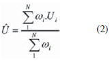 where: Û is the PPV value, Ui represents the instantaneous values of the voltage applied to the tube acquired in N samplings comprising the waveform, and ωi (Ui) represents the values of polynomials defined in the references 11 e 12, weighting each Ui value. In a previous issue of this journal, Terini et al.(15) analyzed the measurement of PPV in the radiological practice. The determination of PPV requires the acquisition of the voltage waveform. In the constant potential equipment utilized at LMRI, the voltage values were directly acquired from the internal voltage divider. Such a divider was previously calibrated by comparison with the end-point value of the x-ray spectra produced by the system, measured, on their turn, by an Amptek, Inc. cadmium telluride (CdTe) detector, as per the experimental and statistical method described by Terini et al.(17). A computer code developed by means of the LabVIEW software allowed for the acquisition of data from the voltage dividers and the calculation of the reference quantities associated with the voltage waveform: kVpabsolute, kVpaverage, PPV, exposure time and ripple. Calibration of the PTW DE2 meter Measurement conditions (beam qualities and standard dosimeters) utilized in the calibration of the DE2 meter are shown on Table 1(18). 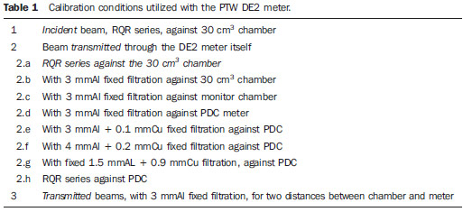 For incident beams, the geometry adopted in the calibration of the DE2 meter is shown on Figure 1A. For the determination of the standard PKA value, the value of the air kerma rate (Ka) measured with the standard chamber was multiplied by the area (A) of the reference collimator aperture (diameter of 8.32 cm), making the correction of the focus-collimator distance (93.5 cm) relative to the focus-detector distance (99.5 cm). In such a case, data collection was done for beams of the RQR(10) series (Table 1, item 1), and then replacing the 30 cm3 chamber by the clinical DE2 meter (Figure 1A). 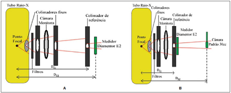 Figure 1. Geometry utilized to calibrate the PTW DE2 meter (A) by the substitution method against the standard 30 cm3 chamber, for incident beams , and (B) by a tandem type method for beams transmitted by the meter. The additional filtration for the RQR series was previously determined. Dfc is the focus-collimator distance (93.5 cm on A and 33.5 cm on(B) and Dfd is the focus-detector distance (99.5 cm). Subsequently, corrections were also made for environmental conditions (temperature and pressure) (kTP), for beam intensity variations, by comparison with the readings from the monitor chamber. The calculation of the calibration coefficients (NPKA) was performed as per equation 3, by means of the ratio between the calculated reference PKA value (PKA,ref) and the value read on the PKA meter under testing (PKA,DE2). 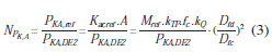 where: Mref, fc and kQ are, respectively, the reading (already corrected for beam variations), the calibration factor and correction factor for the reference chamber beam quality. Then, by using the tandem method(19,20) for transmitted beams, the DE2 meter was placed at 33.5 cm and the standard chamber at 99.5 cm from the focus (Figure 1B). In such a geometry, readings from the meters were simultaneously performed. Besides the RQR series, measurements were performed for transmitted beams with fixed 3 mmAl filtration (Table 1, items 2.a and 2.b). In another series, DE2 meter was also calibrated by utilizing the PTW monitor chamber as a new reference (Table 1, item 2.c) after its previous calibration against the 30 cm3 standard chamber. In such a case, the geometry was selected in such a way that a single beam integrally crossed the DE2 meter and also the monitor chamber placed at 99.5 cm from the focal spot(21). The same previously mentioned corrections were performed in all the measurements. Calibration of the PDC meter The PDC meter was preliminarily calibrated based on the guidance established on the IAEA document TRS 457(1), against the reference PTW 30 cm3 ionization chamber, utilizing the same previous setup, with the Pb collimator with known reference area at 8.5 cm from the detectors testing point (Figure 2A). 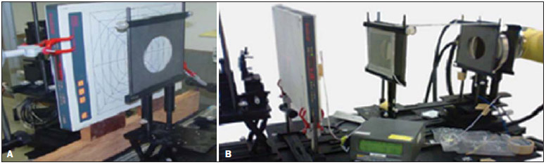 Figure 2. A: Experimental assembly in laboratory for PDC meter calibration for incident beams, utilizing the 30 cm3 chamber as reference. B: Assembly for calibration of the DE2 meter against the previously calibrated PDC meter, for beams transmitted through the DE2 meter. PDC calibration was carried out by the substitution method, utilizing previously characterized standard incident beams of the RQR series and beams with fixed Al and Cu filtration (Table 1, items 2.d to 2.h). The PDC and the reference chamber were alternately positioned at 100 cm from the x-ray tube focus, as shown on Figures 1A and 1B. For the measurement of Ka, the mean Ka values read from the reference chamber were corrected for normal air density. Calibration of the DE2 meter vs. PDC meter With the PDC meter, the calibrations of the DE2 meter became similar to cross calibrations, as the PDC is designed to be previously calibrated in a laboratory and then utilized in the calibration of clinical meters, as in the case of the DE2 meter. Thus, measurements of the DE2 meter calibration against the PDC were performed for RQR beams and with other fixed filtrations recommended by the EURAMET(11) Project (Table 1, items 2.e to 2.g) for inter-comparison. In all cases, simultaneous readings from both meters were done (Figure 2B), applying the appropriate corrections and determining the DE2 meter calibration coefficients as a function of PDC, according to equation 2. In order to verify the influence of the distance on PKA values, other measurements were performed for two different separations between the focus and the collimator (65.5 cm and 42.3 cm). In all cases, combined standard uncertainties were determined in an attempt to identify the contribution of each factor to the total uncertainty. Based on the collected data, it was also possible to analyze the variation of the results with the voltage applied to the tube and with the values of half-value layer (HVL) or semi-reducing layer, as well as the effectiveness of the tandem method(18). Verification of the calibration of a PKA meter in a clinical environment For comparison, and as an application of the calibrated PDC meter in a clinical environment, the verification of a fixed PKA meter (Scanditronix-IBA) calibration was made on a Philips Omni x-ray apparatus at HIAE(9). The PDC, placed on the table in the examination room, was positioned at 80.5 cm distance from the x-ray tube focus. One should observe that, although such a distance does not coincide with the PDC calibration distance, the PKA product, in this limit (as checked), is independent from the mentioned distance. All measurements were performed for exposure times of 200 ms in radiographic mode. PKA values were determined with both meters being simultaneously irradiated, in two measurement series, as follows: 1) varying the tube voltage from 50 to 120 kV, with fixed current-time product of 50 mAs, for three sizes of radiation fields (15 × 15; 20 × 20; and 25 × 25 cm2); 2) varying the current-time product in the range from 2 to 100 mAs, with fixed tube voltage of 81 kV and field size of 20 × 20 cm2, in order to verify the measurements linearity. Calibration coefficients with respective uncertainties were determined for the clinical PKA meter, taking into consideration the PDC calibration performed in the laboratory. Some nominal characteristics of the PKA meters utilized in the present study are: nominal accuracy (k = 2) (DE2: 0.01%; PDC: 10%; IBA: 7%), resolution (DE2: 0.01 µGy.m2 and 0.01 µGy.m2/s; PDC: 1 µGy.m2/min and 0.01 µGy.m2; IBA: 0.1 µGy.m2). RESULTS Results from the PTW Diamentor E2 meter calibration Table 2 shows the results from the previous characterization of the standard RQR beams(10) utilized during the calibrations, by indicating the PPV and 1st HVL (HVL1), homogeneity coefficient (h = HVL1/HVL2), besides the determined additional filtration. 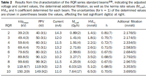 The following results refer to the calibrations performed on the DE2 meter, taking as reference: 1) the 30 cm3 PTW chamber, for incident and transmitted through the meter beams from RQR beams (Table 3 and Figure 3) or with fixed filtration (Table 4); 2) the PTW monitor chamber previously calibrated against the 30 cm3 standard chamber (Figure 4) for beams with 3 mmAl fixed filtration; 3) the Radcal PDC meter previously calibrated against the same standard chamber (Table 5)(22). Lines on the charts are just for visual guidance. 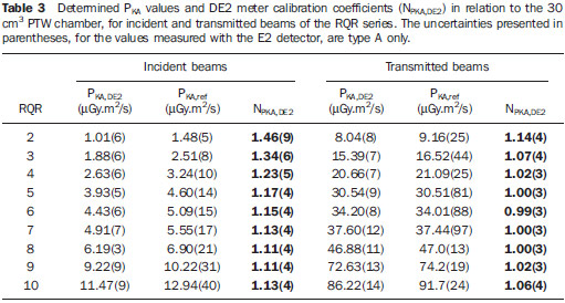 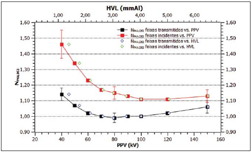 Figure 3. Energy dependence of the DE2 meter calibration for incident and transmitted beams of the RQR series (Table 4), measured against the standard 30 cm3 chamber, as a function of PPV and of the 1st HVL. 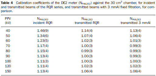 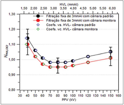 Figure 4. DE2 meter calibration coefficients for beams with 3 mmAl fixed filtration, utilizing as reference the PTW 30 cm3 chamber (black circles) or the PTW monitor chamber (red circles), both as a function of the PPV and HVL. 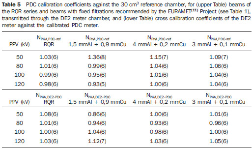 Results from the calibration utilizing the PDC meter Table 5 presents the results of the Radcal PDC meter calibration against the 30 cm3 standard chamber, for beams transmitted through the chamber of the DE2 meter, as well as the calibration coefficients of the DE2 meter, against the previously calibrated PDC, for RQR beams and beams with some fixed Al and Cu filtrations. Table 6 shows an example of the sources (in percentage values) involved in the uncertainty of the calibration coefficients. The uncertainties are always presented for k = 1. 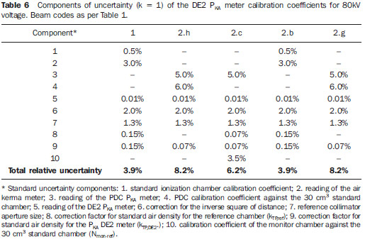 Dependence of the DE2 meter calibration with distance Figure 5 presents the results from the analysis of the variation of the DE2 meter calibration coefficients for two distances to the reference chamber. 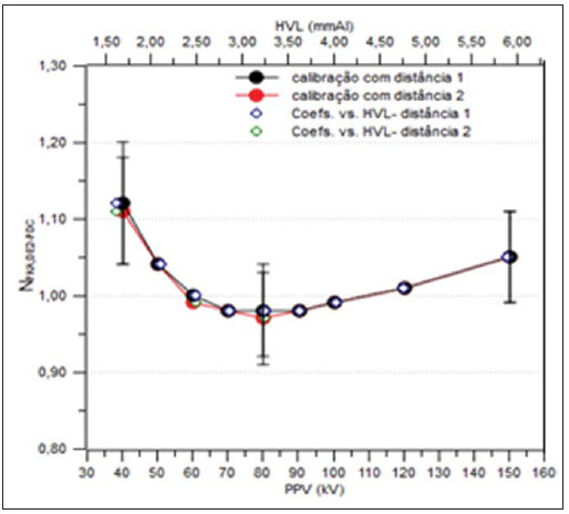 Figure 5. Results of the DE2 meter calibration against the calibrated PDC meter, for beams with 3 mmAl fixed filtration, at two different distances (65.5 cm and 42.3 cm) between focus and PKA meter, (NPKA,DE2-PDC vs. PPV, HVL). Results from a PKA meter calibration in clinical environment against the PDC meter Table 7 shows the results obtained from the measurements performed at HIAE to verify the calibration ("cross" calibration) of a Scanditronix-IBA(9) meter, by comparison with the previously calibrated PDC meter. The PKA values shown on the Table for the clinical meter were not corrected for air density, as both temperature and pressure were not monitored on the site. 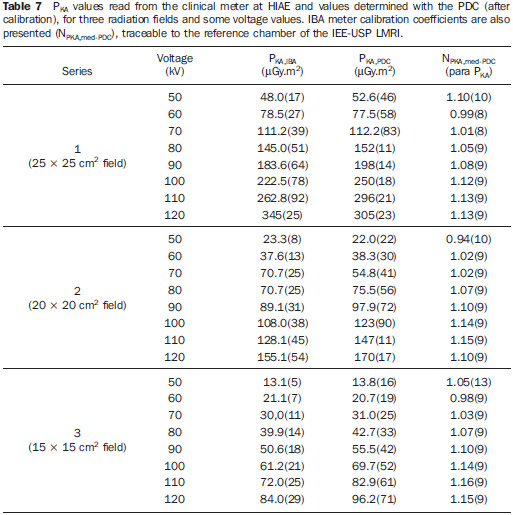 Additionally, in order to analyze the PDC response linearity and compare it with that of the clinical meter, a PKA × mAs chart was built (Figure 6), adjusting a straight line for each data set, by means of the minimum squares method. The uncertainties of all results are shown for the coverage factor k = 1. 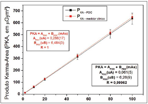 Figure 6. Variation of PKA values as a function of the current-time product (mAs), for the PDC and the clinical IBA meter (linearity curve). DISCUSSION Based on Table 3 and on Figure 3, it is possible to observe that the PTW DE2 meter presents lower energy dependence with beams transmitted through it than with incident beams, coherently with the geometry where it is clinically utilized. Additionally, as shown on Table 4, the energy dependence of the meter for transmitted RQR standard beams is similar to that obtained with 3 mmAl fixed filtration beams utilized in practice. On the other hand, Figure 4 shows that the calibration coefficients for this meter, as the monitor chamber is taken as reference, are systematically lower than those with the 30 cm3 chamber. This fact seems to indicate that, in such cases, the beams that reach the reference meters are different. In fact, one verifies that only the central portion of the x-ray beam reaches the cylindrical chamber, while in the other selected geometry, the same beam that crosses the DE2 meter also reaches the monitor chamber. Also, based on Figure 5, one verifies that within the range of tested distances, there was no significant variation in the meter calibration coefficients. In the analysis of "cross" calibration for different field sizes in clinical situation, it is possible to observe (Table 7) that the analyzed meter presented variations from -6% to +16% in relation to the standard (PDC) for all fields. For the largest field, the meter presented slightly smaller energy dependence. Finally, Figure 6 demonstrates the degree of linearity of both meters (PDC and IBA clinical meter) within the analyzed range in clinical situation. CONCLUSION Measurements performed in the several calibration modes of the PKA meters comprise a great part of the clinical applications of such equipment and aim at comparing its behavior for incident beams and transmitted beams which reach the patient, besides analyzing cross calibrations (as performed in hospitals) and direct calibrations performed in laboratory. Initially, with a view on analyzing the effect of the incident beams on the device, the DE2 meter was calibrated in laboratory by the substitution method against the 30 cm3 chamber. The results on Table 4 show that the energy dependence of the calibration coefficient (NPKA,DE2) is greater for the initial voltages (40 to 60 kV). As the beams transmitted through the meter, both from the RQR series and fixed filtration beams (Table 4) are analyzed, one observes that the calibration coefficient NPKA,DE2 presented more stable values than for incident beams (being practically constant from 60 to 120 kV). Additionally, in such cases, DE2 meter coefficients for RQR beams and those with fixed 3 mmAl filtration were similar. For example, for 60 kV and incident beams, the result was 1.23(5), while with transmitted beams, they were 1.02(3) (RQR series) and 1.01(3) (3 mmAl filtration). On the other hand, Figure 4 shows that, as the calibration reference is modified, different calibration coefficients may be obtained as a function of the difference between the beam that crosses the PKA meter and that which crosses the standard ionization chamber. Thus, it is necessary to verify which situation is closer to that utilized in the clinical practice. In the investigation of the quantities of influence on the calibration results, Figure 5 shows the values obtained for different distances between the focus, PKA meter and reference collimator. For each distance, the area of the beam which will reach the reference chamber is modified. In the investigated range, however, different areas had no significant impact on the calibration results in such a way that the meter can be utilized, at least within the investigated distance limits. In the measurements with the PDC, beams with different fixed filtrations were utilized and, after its previous calibration, the cross calibration of the DE2 meter against the PDC meter was performed, and the characteristics of both meters could be observed. The PDC calibration coefficient (Table 5) tends to be more stable with the voltage (above 80 kV), but the DE2 calibration coefficients present more fluctuations, particularly at higher voltages. This seems to occur due to the composition of the ionization chamber of the clinical meters, which rely on some components with higher atomic numbers in order to reach the desired transparency. The importance of conforming the radiation beams utilized in the calibrations with those applied in the clinical practice becomes noticeable as data on Table 5 are observed. Beams with different filtrations, utilized in different radiological procedures, produce significantly different calibration coefficients for the DE2 detector, and the difference increases with the thickness of additional filtration. At the same time, Table 6 demonstrates that the component which most affects the calibration uncertainty is the very reading of the calibrated instruments and the calibration coefficients of the reference chamber. As regards temperature and pressure, at the first measurements an Oregon meter was utilized, with a participation of 0.15%. Such participation decreased to 0.07% as the Oregon meter was replaced by a Fluke meter. The PDC device presented a greater nominal uncertainty in the readings (5.0%) than with the utilization of the monitor chamber (3.5%). The participation of this portion, when the DE2-PDC cross calibration is performed, is higher, since the uncertainties propagate. From the data on Tables 5 and 7, one observes a smaller energy dependence of the PDC (+4% to 3%) as compared with the DE2 meter (+14% to 2%) and with the tested clinical PKA meter (2% to +16%), with the calibration factors of the latter presenting a tendency to increase with the tube voltage, in all evaluated field areas. On the other hand, both the PDC and the analyzed clinical PKA meter present an excellent linearity within the investigated intensity range (up to 700 µGy.m2, with R ≈ 1) (Figure 6). Uncertainties inherent to PKA meters calibration are typically high, but the accuracy of the conventional calibration method (which utilizes ionization chamber + film) may, in fact, be improved by utilizing a PKA meter calibrator, such as the PDC as clinical reference, provided it has previously been calibrated in a standard laboratory, in such a way it can be utilized in cross calibrations of other PKA meters. It is obvious that whenever the calibration of the clinical meter can be directly made in laboratory, the accuracy will tend to be higher. In the European Community, the utilization of the PKA meters has been mandatory from several years(23). In Brazil, there are still no regulation regarding this issue, and currently only a limited number of institutions have such devices installed in their x-ray systems. Also, few studies on the subject are found in the literature. On the other hand, IAEA has been emphasizing the PKA quantity for the improvement of dose monitoring, considering the high number of reports on radiological accidents caused by inappropriate procedures. The utilization of PKA meters is an excellent alternative for monitoring of doses on patients in clinical procedures, by clinical and technical teams; however, such meters must be periodically calibrated, which is normally a responsibility of a medical physicist. One of the objectives of the present study has been to study the calibration of such type of instrument, both in laboratory and in a clinical environment with a view on raising the awareness on this matter in the country and the implementation of such service in the LMRI of IEE-USP. Acknowledgements The authors wish to thank Hospital Israelita Albert Einstein and the Master of Physics Marcia Carvalho Silva, for making the clinical measurements possible; to Nuclear Tech and Radcal Co. for loaning the PDC device for the tests; to Fundação de Amparo à Pesquisa do Estado de São Paulo (Fapesp) and to Conselho Nacional de Desenvolvimento Científico e Tecnológico (CNPq), for the partial financial support; and to LMRI-STDTS-STAMH (IEE-USP), for the support from the staff and for the utilization of their infrastructure. REFERENCES 1. International Atomic Energy Agency. Dosimetry in radiology: an international code of practice. Technical Reports Series n° 457. Vienna: IAEA; 2007. 2. International Electrotechnical Commission. Dose area product meters. 2nd ed. Geneva: IEC; 2000. 3. nternational Comission on Radiation Protection. The 2007 Recommendation of the International Commission Radiological Protection. Ann ICRP. 2007;37(2-4). 4. Hart D, Jones DG, Wall BF. Estimation of effective dose in diagnostic radiology from entrance surface dose and dose-area product measurements. Report NRPB-R262. London: HMSO; 1994. 5. International Commission on Radiation Units and Measurements. ICRU Report 33. Radiation quantities and units. Bethesda: ICRU; 1980. 6. Toroi P, Komppa T, Kosunen A, et al. Effects of radiation quality on the calibration of kerma-area product meters in x-ray beams. Phys Med Biol. 2008;53:5207-21. 7. Canevaro LV. Aspectos físicos e técnicos da radiologia intervencionista. Rev Bras Fís Méd. 2009;3:101-15. 8. Toroi P, Kosunen A. The energy dependence of the response of a patient dose calibrator. Phys Med Biol. 2009;54:151-6. 9. Almeida Jr JN, Silva MC, Terini RA, et al. Estudo da calibração indireta de medidores clínicos do produto kerma-área. Rev Bras Fís Méd. 2011;4:75-8. 10. International Electrotechnical Commission. Medical diagnostic x-ray equipment: radiation conditions for use in the determination of characteristics, IEC 61267. Geneva: IEC; 2005. 11. EURAMET (European Association of National Metrology Institutes). Comparison of calibration of KAP meters in terms of air Kerma area product, ref. 1177, (EURAMET Project), 2011. 12. Kramer HM, Selbach HJ, Iles WJ. The practical peak voltage of diagnostic x-ray generators. Br J Radiol. 1998;71:200-9. 13. International Electrotechnical Commission. Medical electrical equipment - Dosimetric instruments used for non-invasive measurement of x-ray tube voltage in diagnostic radiology. IEC 61676 Standard. Geneva: IEC; 2002. 14. International Commission on Radiation Units and Measurements. ICRU Report 74. Patient dosimetry for x-rays used in medical imaging. Oxford: University Press; 2005. 15. Terini RA, Potiens MPA, Herdade SB, et al. A medição da grandeza practical peak voltage na prática radiológica. Radiol Bras. 2009;42:389-94. 16. Hetland PO. et al. Calibration of reference KAP-meters at SSDL and cross calibration of clinical KAP-meters. Acta Oncol. 2009;48:289-94. 17. Terini RA, Pereira MAG, Kunzel R, et al. Comprehensive analysis of the spectrometric determination of voltage applied to X-ray tubes in the radiography and mammography energy ranges using a silicon PIN photodiode. Br J Radiol. 2004;77:395-404. 18. Campelo MCS, Terini RA, Herdade SB, et al. Analysis of different methods for calibration of PKA meters on laboratory. In: IFMBE Proceedings. 2012;39:1160-3. World Congress on Medical Physics and Biomedical Engineering (WC2012, Beijing). 19. Toroi P, Komppa T, Kosunen A. A tandem calibration method for kerma-area product meters. Phys Med Biol. 2008;53:4941-58. 20. Malusek A, Carlsson GA. Analysis of the tandem calibration method for kerma-area product meters via Monte Carlo simulations. Standards, Applications and Quality Assurance in Medical Radiation Dosimetry (IAEA), 2010;129-36. 21. Almeida Jr JN, Terini RA, Pereira MAG, et al. Calibration of PKA meters against ion chambers of two geometries, Rev Bras Fís Méd. 2011;5:15-20. 22. Campelo MCS, Terini RA, Pereira MAG. Análise da calibração de medidores de PKA em um laboratório padrão. In: XVII Congresso Brasileiro de Física Médica, Salvador. Anais do XVII CBFM; 2012. 23. European Commission. Council directive of June 30, 1997 (97/43/Euratom) on health protection of individuals against the dangers of ionizing radiation in relation to medical exposure. Official J Eur Commun No. L180/22; 1997. 1. PhD of Physics, Full Professor, Pontifícia Universidade Católica de São Paulo (PUC-SP), São Paulo, SP, Brazil 2. Graduate Student of Physics, Pontifícia Universidade Católica de São Paulo (PUC-SP), São Paulo, SP, Brazil 3. Bachelor of Physics, Undergraduate Student of Physics at Pontifícia Universidade Católica de São Paulo (PUC-SP), São Paulo, SP, Brazil 4. Private Docent of Physics, Consultant, Instituto de Energia e Ambiente da Universidade de São Paulo (IEE-USP), São Paulo, SP, Brazil 5. PhD of Sciences (Nuclear Technology - Applications), Head of Section, Instituto de Energia e Ambiente da Universidade de São Paulo (IEE-USP), São Paulo, SP, Brazil Mailing Address: Dr. Ricardo Andrade Terini Rua Marquês de Paranaguá, 111, Consolação São Paulo, SP, Brazil, 01303-050 E-mail: rterini@pucsp.br Received February 21, 2013. Accepted after revision June 25, 2013. Study developed in the Laboratory of Ionizing Radiations Metrology at Instituto de Energia e Ambiente da Universidade de São Paulo (IEE-USP) - São Paulo, SP, Brazil. |
|
Av. Paulista, 37 - 7° andar - Conj. 71 - CEP 01311-902 - São Paulo - SP - Brazil - Phone: (11) 3372-4544 - Fax: (11) 3372-4554